-
 DIY Hydronic system automation controller
The last day and half have been a big wiring project for the DIY hydronic heating system that I have been working on.
Anyway, heres the layout that I came up with, bit more of a rats nest then I originally planned, but hey working on getting it wrapped up and done!!!
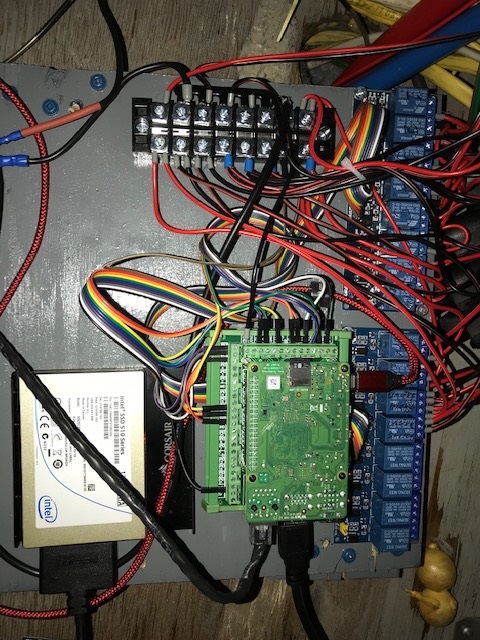
Also, I am running out of bay wall space. So, I pre-wired everything up on a one-foot square board with extra-long wiring leads and mounted it to the ceiling of the plumbing/electrical bay.
Your basic Raspberry Pi driving two eight channel relay boards. I went with a left over SSD drive for long term reliability; as the typical SDCard can wear out in 2-3 years or sooner depending on the write cycle frequency. Plus the SSD drive is faster...
The functions that it is currently controlling is:
- Bedroom heater zone pump.
- Bathroom heater zone pump.
- Kitchen heater zone pump.
- Living room heater zone pump.
- Front bays freeze protection pump.
- Rear bays freeze protection pump.
- Stir/circulation pump.
- Pump for Engine preheating and thermosiphon heat recovery.
- Pump for Generator preheating and thermosiphon heat recovery.
- Diesel Boiler remote on/off.
- Electric ball valve to force flow through the diesel boiler when it is on, bypass when off.
- Temperature sensor for hydronic tank output.
- Temperature sensor for Engine coolant, thermosiphon heat recovery monitoring.
- Temperature sensor for generator coolant, thermosiphon heat recovery monitoring.
I still have four relays left over and could add another eight-channel relay board for $10.00 before I max out the Raspberry Pi. All told this could be duplicated for around $120.00
Once all the hardware is installed then its software time!!! Something I do everyday in my day job.
Starting with a simple manual over-ride web page with simple touch buttons for each relay function.
Software wise in the long term will be smart scheduling and Alexa voice control integration. Which is easy to do with Internet of Things Node Red software.
 Posting Permissions
- You may not post new threads
- You may not post replies
- You may not post attachments
- You may not edit your posts
-
Forum Rules


 Reply With Quote